However, blue parts are hard to find! Most of the custom colours are red, silver, black or silver. Very few blue parts are available. I managed to find some blue Litepro chainring bolts, to use on the front single crankset.
For this bike, other than the blue wheelset and the blue chainring bolts, I wanted to change the seatpost clamp and the headset to blue colour. This would be similar in idea to how I wanted to add red colour to the Dahon MuEX last time.
There are only a few sources with blue parts on Taobao, and you will not know if they really have it in stock, until you actually order it. Therefore I just have to try my luck and place the order...

Blue seat post clamp is available! Looks very much like the Dahon design which is good.

Looks good on the black frame. Although it will look better if the logo is removed...

Blue headset shown in the top row, with the Litepro headset shown at the bottom row.
The blue headset is from some generic brand with no logo. The construction is of an older design, which has more parts as compared to the Litepro headset which is much simplified. The part that can actually be seen is only the blue headset cover, therefore I mixed and matched the two headset to get the best combination that matches both the frame and the fork.

With the blue headset cover installed! Good contrast with the black frame and handlepost.

Frame, fork and handlepost installed, along with the blue headset cover and seat post clamp.
At this point in time, I was actually still waiting for the blue Wheelsport wheelset to be available as it was out of stock, which is why I could not start some parts of the assembly yet. However, I could install some other parts that are not directly dependent on the wheelset.

Ultegra R8000 brake calipers installed at the rear of the frame, using the dedicated caliper brake mount.

The brake calipers are also installed on the front fork, also using the dedicated caliper brake mount.
Before installing all the components, it is a good idea to connect up the Di2 components to make sure they are working properly. This is especially important since the internal routing will make it more difficult to troubleshoot if something does not work.
Di2 wiring layout on the Dahon MuSP. Note that the wireless unit and Junction A are actually placed in between the left and right shifters, which is unconventional.
In this layout, the 1000mm, 150mm, 300mm, 700mm Di2 wires are fully internal routed, while the 1400mm Di2 wire is partially internal routed through the main frame. As shown below, the 1000mm Di2 wire, wireless unit and 150mm Di2 wire are fully hidden within the handlebar.

Full Di2 layout tested on actual components to check if they are working properly. No problem!

Shown here is the right side bar end. The 1000mm Di2 wire (peeping out from the handlebar) comes from the left side shifter, through the handlebar, and is connected to the wireless unit. The short 150mm Di2 wire will be connected to Junction A.

Before pushing the wireless unit into the handlebar, it is first wrapped in sponge to prevent rattling inside the handlebar. Might be difficult to get it out next time...

The 150mm Di2 wire is then connected to Junction A. The other 300mm Di2 wire will pass through the hole at the handlebar, and run along the outside of the handlebar, up to the right shifter.

Once again, connecting everything to make sure it is working properly. Remember to install the Controltech stem before you install the shifters!

At the same time, I also connected the Garmin Edge 510 to the Di2 system, to display the selected gear. It works fine!
Now I know that the handlebar area of the bike is working fine, the next step is to wire up the rest of the bike. More specifically, connecting the Di2 rear derailleur, battery and Junction B together, before linking up with the handlebar.
This part is quite challenging, as it also requires the internal routing kit to help pull the cables and wires through the frame. I started with the 700mm Di2 wire, which is the one that links the Di2 rear derailleur with Junction B, and is routed internally through the right side seat stay.
Routing this Di2 wire from the seat stay side should be easier, as the hole at the seat stay side is small, while the frame hole near the joint area is bigger. It is always easier if the cable/wire exits from a larger hole.

View from the frame joint, looking back towards the seat tube and seat stays. It seems that the seat stay and main frame is not connected internally, but it actually is, through a small hole as seen on both sides of the seat tube.
Routing the Di2 wire through the small hole between the seat stay and the main frame is quite tricky, luckily I had an internal routing kit which uses a strong magnet to help guide the wire along the correct path.
The 500mm Di2 wire links the external Di2 battery to Junction B, which will be located internally inside the main frame. This wire will enter the frame through the hole for the rear brake cable.
At the other end, the long 1400mm Di2 wire will enter the main frame near the head tube area, and exit at the frame joint. Same path is taken for the rear brake cable.
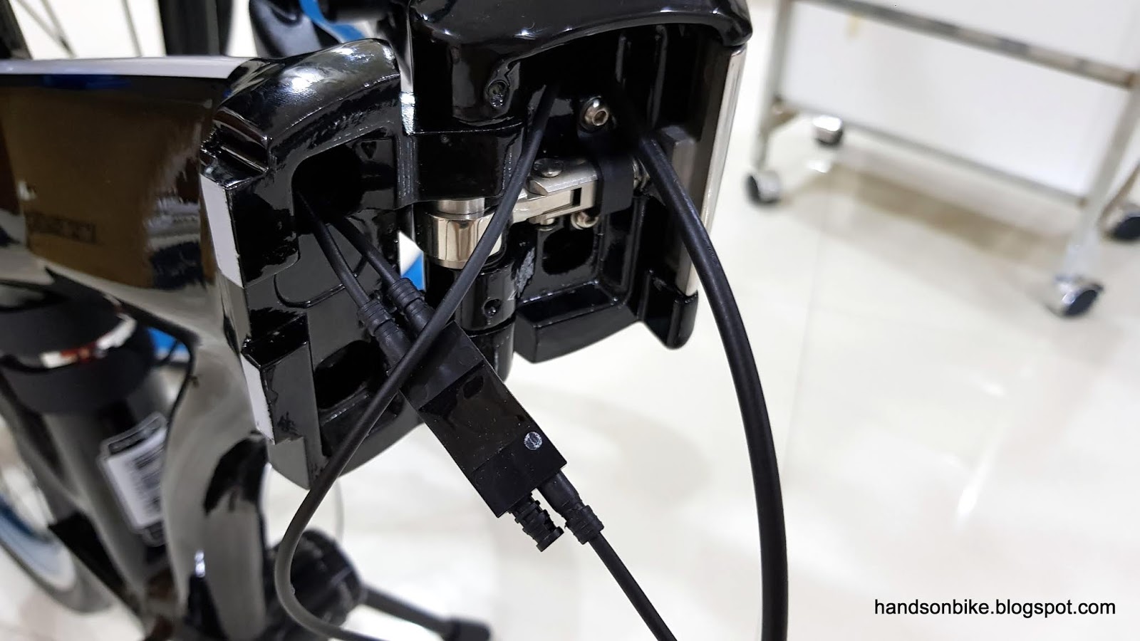
After much work, the Di2 wires can be connected at the frame joint area! The two wires from the left comes from the battery and the rear derailleur, while the one from the right is connected to the handlebar area.
Once again, the components are tested to make sure they are working at this stage. Once done, the Junction B needs to be stored inside the frame, at the rear part of the main frame (near the seat tube).
In order to prevent rattling sounds, I will need to prevent Junction B from hitting the inside of the frame. I wanted to wrap Junction B in sponge, but I found that it does not fit into the hole after wrapping it in sponge. The other way is to stuff sponge inside the frame, to act as padding along the internal walls of the frame.

Junction B inserted into the frame, in between the sponge. The brake cable will also run through this hole, beside the sponge and Junction B.
All these internal routing takes a lot of time and effort, especially since this frame is not designed for internal Di2 wiring. I would prefer not to do it again, as it is quite a lot of trouble.
More assembly to be done! To be continued in the next post.
No comments:
Post a Comment
Every comment is moderated before publishing due to spam bots. If you don't see your comment yet, it is likely that it is currently being reviewed. Thank you for your patience!