Frame and fork
Handlepost and handlebar
Hydraulic brake system
451 wheelset and tires
Actually, if you look at it this way, there are many new components. Only the drivetrain and shifting components could be transferred over from the Dahon MuEX.
Previously, when I was building the Crius AEV20 1x11 speed folding bike from scratch, I found that the head tube was not round, which caused some difficulties for pressing in the headset cups. I was worried that this Fnhon frame might have the same issues, as the quality control of these brands (Crius, Fnhon) might not be as good as more established brands such as Tern or Dahon.
As shown previously, the head tube of this Fnhon frame is not too bad, it should not give me any big problems. Therefore, I was able to press in the headset cups quite easily, while the sealed bearings could also be placed into the cups by hand.

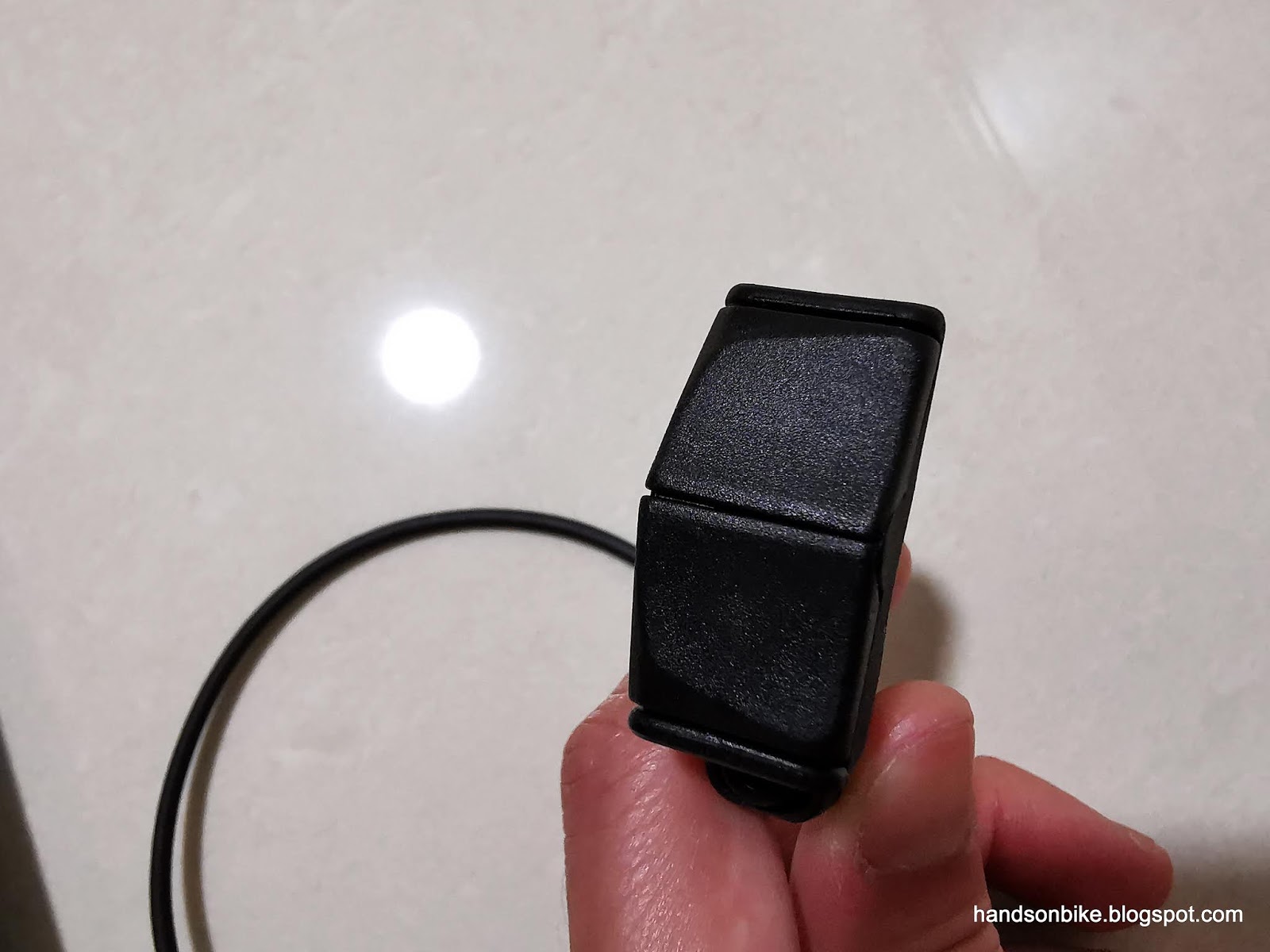
Headset sealed bearings placed into the top headset cup.

The tried and tested Litepro headset which I have used for almost all my folding bikes. Standard protrusion length of the steerer tube for Dahon/Fnhon handleposts.
If you want to install a stiffer Tern Physis handlepost, it is possible, but you will need a fork with a longer steerer tube. More details of how I experimented with it on the Dahon Boardwalk here.

As the new Fnhon handlepost has a taller base, the steerer tube appears to be too short.

Which is why the new Fnhon handlepost also comes with a longer compression bolt (bottom) which will enable it to be compatible with standard steerer tubes.

With the fork, handlepost and handlebar installed!
There is a compatibility problem between the new XTR BL-M9120 brake lever and the XTR Di2 SW-M9050 shifting switch. The new brake lever uses the I-Spec EV clamp band, which moves the clamp band position inwards on the handlebar. This causes it to interfere with the XTR Di2 shifting switch, which takes up quite a bit of space on the handlebar.
Compatibility Chart:
Standard BL + Di2 Firebolt Switch = OK
I-Spec EV BL + Di2 Firebolt Switch = Not compatible
In this case, I have to change to another type of Di2 shifting switch, as the XTR Di2 Firebolt cannot be used. Another way is to stick to conventional brake levers with the usual clamp band position (beside the Grip).
Luckily, there are alternative Di2 shifting switches available, such as those from the E-bike series. Those switches are smaller which will be compatible to the I-Spec EV brake lever.

Di2 shifting switch from the E7000 E-bike series. 300 mm refers to the length of the built-in Di2 wire.

The switch weighs just 20 grams! Lighter than the Di2 Firebolt switch which weighs 64 grams each.

Construction is quite simple, with a steel clamp band and a clamp bolt to secure it to the handlebar.
The operation method is straightforward, with just 2 buttons on top and below. The buttons have a slight tilt to the right side for more ergonomic operation.

The side with the printed logo should face upwards.

It comes with 3 high tech rubber bands for neater wire management on the handlebar.

Di2 switch installed beside the Grip for comfortable operation.

With the Di2 wires managed properly, it looks very neat from the top! Note clamp band position of the I-Spec EV brake lever, and also the 2 rubber bands on the handlebar to secure the loose Di2 wires.

Di2 wires hidden under the handlebar and brake lever, to hide the clutter. Di2 wire will run along the rear brake hose to the rear of the bike.

Di2 battery mounted behind the seat tube as done previously on the Dahon MuEX and Dahon MuSP.

Di2 wiring layout of the Fnhon DB11. Note the new Di2 switch and the Dura-Ace Di2 rear derailleur!
Why did I use the Dura-Ace Di2 rear derailleur? The previous Ultegra Di2 rear derailleur from the Dahon MuEX was working perfectly fine. However, ever since I swapped the rear derailleur on the Canyon Endurace to GRX Di2, the Dura-Ace Di2 rear derailleur has been lying around unused. Instead of having such a good component in the storeroom, I might as well put it to good use, and so here it is on the Fnhon DB11! As a bonus there is a weight savings of about 60 grams.
Earlier on, I talked about the usage of 140 mm disc rotor at the rear. I wanted a smaller rotor to reduce the braking power, as small wheels can achieve high braking power even with smaller rotors. On the front, the geometry limits the smallest rotor to 160 mm diameter, but for the rear, 140 mm rotor is possible.
Now, after I installed the new kickstand, I found that a smaller 140 mm rotor at the rear is necessary to prevent interference with the kickstand. A 160 mm rotor would not have been possible. Let me show you why.

With the kickstand installed, the front interferes with the left crankarm, while the rear interferes with the 140 mm diameter rotor.

The kickstand will touch the left crankarm if the kickstand is rotated outwards slightly to clear the rear rotor.

On the other hand, if the kickstand is rotated inwards to clear the left crankarm, the kickstand will touch the rear 140 mm rotor instead.
It seems that there is no way to install the kickstand, without having it interfere with either the left crankarm or the rear 140 mm rotor. However, I had an idea to lower the kickstand slightly, to provide more clearance. I added a spacer under the kickstand mount, so that the entire kickstand is lowered relative to the bike frame.

Spacer added under the frame, to lower the position of the kickstand. This spacer is just a squashed plastic cassette sprocket spacer.

With the addition of this spacer, the kickstand position is lowered slightly, but still constrained by the side walls to prevent kickstand rotation.

Now, the kickstand can be rotated inwards more, and still clear the rear 140 mm rotor and also the rear wheel spokes. It also just manages to clear the left crankarm. Not much clearance though.
With this, I was able to install the kickstand, and still maintain clearance with the left crankarm and also the rear 140 mm rotor. If the rear rotor had been bigger at 160 mm, it would touch the rubber leg of the kickstand.

I tried to put a magnet on the left pedal axle, so that it can be used for the cadence sensor. However, there is not enough clearance between the magnet and the left chain stay.

As you can see, there is actually very little clearance between the left crankarm and the left chain stay. I don't remember having such a small clearance on the Dahon MuEX.
At this point, assembly of the Fnhon DB11 is almost completed. There were less issues compared to what I encountered on the Crius AEV20, which is good news.
No comments:
Post a Comment
Every comment is moderated before publishing due to spam bots. If you don't see your comment yet, it is likely that it is currently being reviewed. Thank you for your patience!